What is a Centrifugal Pump?
A centrifugal pump is a pressure-producing device used to move liquids from one location to another in a variety of industrial and commercial applications. It turns velocity energy into pressure, and the resulting flow is determined by the system's properties.
What Are Centrifugal Pump Curves?
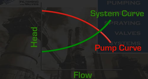
The performance of a centrifugal pump in terms of pressure head and flow rate can be seen clearly in a centrifugal pump curve. It's a graph of the pump's head vs. flow. When choosing a pump for a new application, several considerations should be taken into account. The Best Efficiency Point (BEP) is one of the most important factors to consider here. At any specific impeller diameter, this is the region on the curve when the efficiency of the pump is at its best, and the maximum amount of axial and radial loading is minimized. While it would be ideal to be able to size pumps to function at BEP in all circumstances, this isn't always possible due to application constraints.
Pumps that are operated too far away from this point may fail prematurely. The following are some of the issues that can arise as a result of this:
- Wastage of time and money
- Excessive vibration
- Premature pump parts wear and tear
- Cavitation
Reading pump curves can be a difficult undertaking, as various types of pumps correlate to different sorts of curves. This article looks to end that confusion by providing the basics on how to read and use centrifugal pump curves.
What Does Reading Centrifugal Pump Curves Entail?
Mechanically, a centrifugal pump is a pretty basic device. However, reading the centrifugal pump curve is a different thing.
A centrifugal pump is made up of an impeller connected to a shaft that is turned by a driver, which is usually an electric motor. There is only one moving part, excluding the shaft and bearings.
A centrifugal pump transfers energy to a liquid and has flow and head characteristics that are based on the system. The pump needs to overcome a certain level of pressure which will determine the operating point on the curve and how much flow will be generated.
For most centrifugal pumps, flow reduces as pressure rises, pushing your performance point to the curve’s left. The performance point moves to the curve’s right as pressure drops and flow rises.
There are numerous aspects to take into account when looking at curves for a new application. However, in most circumstances, a choice should be made as close as practicable to the BEP.
How to Read and Use Centrifugal Pump Curves?
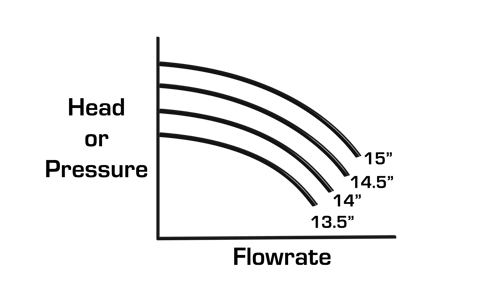
Figure 1
Pump curves in general represent the pump’s ability to develop a flow with respect to pressure or head; there can be many separate curves shown on the same plot. Each usually represents a change in pump speed or impeller diameter. In this case (Figure 1), the pump speed remains constant, and we are varying the impeller diameter.
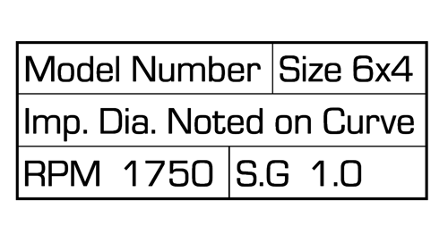
Figure 2
There are several important features on the sheet (Figure 2):
- The data block which notes the pump model
- Suction and discharge port sizes
- Impeller diameter
- Pump speed in rpm
- Sometimes the specific gravity of the liquid that the pump was tested on, which is usually 1.0 which corresponds to water
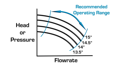
Figure 3
Also shown on the curve (Figure 3) is the recommended operating range, shut-off head and run-out.
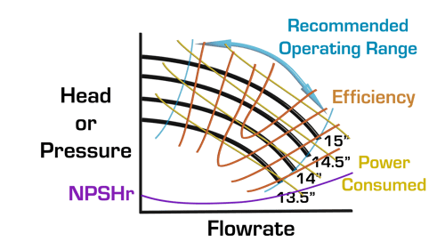
Figure 4
Other important information often shown (Figure 4) is:
- The power consumed
- The efficiency
- The Net Positive Suction Head Required by the pump (NPSHr)
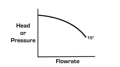
Figure 5
Let's now look at a single curve (Figure 5) and see how it can be used in a real pumping application.
First, ensure the pump curve corresponds to the actual pump speed and impeller diameter.
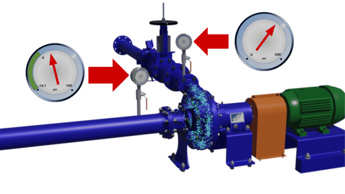
Figure 6
Once this is confirmed (Figure 6), we can then take the discharge gauge reading and subtract the suction gauge reading to get the total dynamic head (Figure 7) that is being generated by the operating pump.
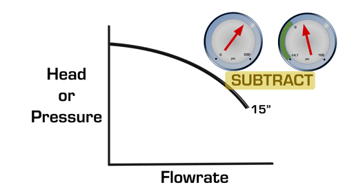
Figure 7
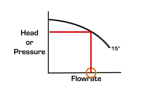
Figure 8
We can now take this value and plot it on the pressure or head axis. Doing this gives us an estimated flow rate (Figure 8). For this to be accurate, the pump must be in factory new condition. Also, the pumped fluid must not have any air entrainment, and finally, the pump cannot be suction cavitating.
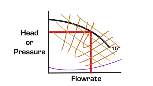
Figure 9
Other important values like efficiency, power consumed, and net positive suction head required can also be estimated (Figure 9).
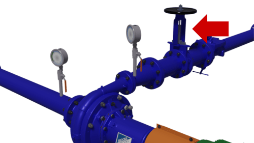
Figure 10
In this setup, we can also simulate the pump having to operate at higher back-pressure by partially closing a downstream valve (Figure 10).
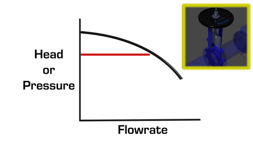
Figure 11
However, we must be cautious that we do not increase the total dynamic head beyond the recommended operating region (Figure 11).
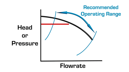
Figure 12
Again, subtract the suction gauge from the discharge gauge and plot the value on the curve (Figure 12).
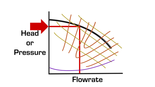
Figure 13
A new flow rate along with efficiency, power consumed and NPSHr required can now be estimated (Figure 13).
Reading pump curves becomes easier with practice, especially if you have to deal with various types of pumps. Feel free to refer to this guide every time you need to read a centrifugal pump curve.
John Brooks Company Is a Prime Source of Centrifugal Pumps
At John Brooks Company, we provide standard and custom-built centrifugal pump solutions for a wide range of commercial, municipal, and industrial processes, including food manufacturing, mining and mineral processing, and more.
With a massive selection of centrifugal pumping systems from leading manufacturers and the valuable input from our application experts, we guarantee the best fit for your unique application.
Contact us today to learn more or to book a consultation with one of our experts.
